Correctly integrating a motor controller is a critical step in achieving reliable system performance. Errors during installation can lead to operational issues or component damage. Santroll have developed a structured approach to this procedure for our range of Electrical Motor Products. Wiring an ac motor and controller requires careful attention to documentation, safety, and terminal identification to ensure a secure and functional connection.
Initial Preparation and Safety Protocol
Before handling any components, a comprehensive review of the system documentation is essential. This includes the manuals for both the motor and the controller. Verify that the voltage and current ratings of the ac motor and controller are compatible with each other and with the available power supply. The initial physical step involves ensuring all power sources are completely disconnected and locked out. Confirm that any capacitors in the system have been given adequate time to discharge. Using the correct tools, such as a voltage tester to validate the absence of power, is a non-negotiable safety practice. This preparatory phase mitigates the majority of potential risks associated with the installation of Electrical Motor Products.
Executing the Power Circuit Connections
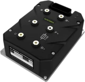
The power stage involves three main sets of connections: input power, output to the motor, and grounding. Begin by connecting the mains power supply wires to the controller’s designated input terminals (often labeled L1, L2, L3 for three-phase systems). Next, run the output wires from the controller’s motor terminals (frequently labeled U, V, W) directly to the corresponding terminals on the motor itself. It is crucial to follow the manufacturer’s torque specifications for terminal screws to prevent loose connections that can arc or overheat. A dedicated ground wire must be connected to both the controller’s grounding terminal and the motor’s grounding point, creating a vital safety path for fault currents.
Integrating Control and Feedback Signals
With the high-power circuit established, the control wiring can be addressed. This low-voltage section manages the controller’s operation. These connections typically include a digital input for a run/stop command, a potentiometer or analog input for speed reference, and potentially a direction signal. Shielded cable is often recommended for analog and communication lines to protect against electrical noise from the power wires. If the system uses a feedback device, such as an encoder on the motor, it must be wired to the controller’s feedback module according to the pinout diagram. The integrity of these signals directly affects the precision and functionality of the ac motor and controller system.
A successful installation is verified not by the completion of wiring alone, but by a systematic startup procedure. Once all connections are double-checked for correctness and tightness, power can be applied in a controlled manner. Many modern controllers allow for parameter initialization without enabling the motor drive. Use this feature to confirm that control signals are being received correctly. The first activation of the motor should be a brief test at a very low speed to confirm correct rotational direction and absence of unusual noise. This meticulous approach to wiring and commissioning ensures that our electrical motor products deliver their intended performance and longevity, forming a dependable foundation for your application’s motion requirements.