Industrial maintenance teams require effective strategies for addressing malfunctions in drive systems. When a variable speed controller for AC motor exhibits faults, a phased procedure can identify the root cause. This method focuses on measurable electrical values and observable system behaviors to guide the diagnostic process.
Phase One: Input Power and DC Bus Verification
Begin with quantitative measurements of the incoming power supply. Use a true-RMS multimeter to confirm that all AC input phases at the motor controller terminals are within the specified voltage range and balanced. A voltage imbalance exceeding 2% can trigger faults. After confirming input, investigate the DC bus, which is the foundation for the output stage. A functioning variable speed controller for AC motor will maintain a stable DC bus voltage, typically 1.35 times the RMS input voltage. A significantly low or absent bus voltage points to rectifier circuit failure or DC bus capacitor degradation, which is a common source of undervoltage faults.
Phase Two: Output Stage and Load Circuit Analysis
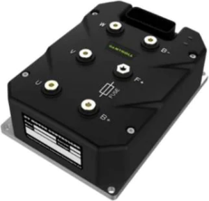
With input power validated, examine the output path. Safely disconnect the motor and use a megohmmeter to test for insulation breakdown between the windings and the motor frame. Resistance readings below the manufacturer’s specification indicate a ground fault. Next, with power off, use a multimeter to check for short circuits between the output phases (U, V, W) at the motor controller terminals. Low resistance here suggests failed output IGBTs. For a variable speed controller for AC motor, these power semiconductor failures are a primary cause of overcurrent faults. Reconnect the motor only after these checks confirm circuit integrity.
Phase Three: Control Signal Validation and Parameter Audit
Many operational failures originate in the low-voltage control circuit. Verify digital inputs like “Run” and “Enable” by measuring for the presence of the specified voltage (e.g., 24 VDC) at the control terminals when the command is active. For analog speed reference, use a multimeter to confirm the signal (0-10V or 4-20mA) corresponds to the expected speed command from the PLC. Signal noise or loss here will prevent operation. Finally, audit the parameter set of the motor controller. Incorrectly entered motor nameplate data (full load current, base speed) or improperly set acceleration ramps can cause performance issues and unexpected faults, even if all hardware components are functional.
This phased procedure—power verification, output inspection, and control signal audit—creates a logical fault isolation path. It distinguishes between component failure within the motor controller, external load problems, and configuration errors. The variable speed controller for AC motor provides the measurement points and parameters needed for this analysis. We at Santroll design our systems to support this diagnostic workflow, with clear terminal markings and accessible test points. Applying this structured approach reduces diagnostic time, prevents unnecessary parts replacement, and returns drive systems to operational status with greater confidence in the repair’s longevity.