Equipment downtime demands a swift and accurate response, with the motor controller often being a primary component for evaluation. We have developed a diagnostic framework for our technical teams to assess the functional state of a motor controller. This methodology applies to various types, including a standard AC electric motor controller. Applying this logical sequence helps identify whether the issue resides within the controller itself or elsewhere in the system.
Initial Power and Indicator Analysis
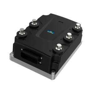
The first layer of diagnosis involves basic power supply verification. Confirm that the correct input voltage is present at the controller’s terminals using a multimeter. An absence of power here shifts the focus upstream to breakers, fuses, or contactors. With power applied, observe the controller’s status indicators. Most modern units, including our Santroll controllers, provide specific LED sequences or alphanumeric codes that signal operational status or active faults. A controller with no illuminated indicators suggests a primary power circuit issue, while a device showing an active fault code provides a direct starting point for further investigation. This step efficiently separates power supply problems from internal controller malfunctions.
Control Signal Verification and Command Processing
A motor controller requires correct input signals to function. If the unit powers on but does not drive the motor, the investigation must extend to its control circuits. Using the technical documentation, check for the presence of the enable or run signal. Verify that speed reference signals, whether analog (0-10V) or digital (pulse train), are present and match the expected values from the PLC or control system. A simple oversight in control wiring or a missing enable command is a common reason for a perceived controller failure. For an AC electric motor controller, ensuring that the control logic matches the configured input type is a necessary step before proceeding to more complex diagnostics.
Output Stage Evaluation under Controlled Conditions
If power and control signals are confirmed, the output stage of the motor controller requires examination. This must be performed with extreme caution and preferably with the motor disconnected to prevent unexpected movement. Using a true-rms multimeter or an oscilloscope, check the voltage at the output terminals (U, V, W) during a run command. A functioning AC electric motor controller will produce a balanced three-phase output voltage that corresponds to the commanded frequency. Significant imbalance, distorted waveforms, or a complete lack of output voltage indicates an internal fault within the inverter stage. Additionally, checking for short circuits or ground faults at the output terminals with power disconnected can reveal insulation breakdown.
This diagnostic path—from power supply to control signals to output validation—creates a clear decision tree for technicians. Isolating a fault to the motor controller itself prevents unnecessary component replacement and reduces system downtime. Our design philosophy emphasizes such diagnosability, providing clear feedback through status indicators and logical terminal layouts. A structured approach to testing the motor controller ensures that maintenance actions are precise, cost-effective, and restore operation with confidence.