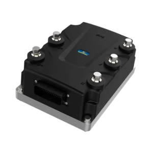
Electrical power conversion is a fundamental operation in modern drive systems. Many applications utilize DC power sources, such as batteries or rectified line power, yet require AC power to run induction motors. The device that performs this essential transformation is a motor controller, specifically an AC electric motor controller. We will outline the functional stages this controller uses to generate a controlled AC waveform from a DC input.
Initial Stage: Establishing a Stable DC Bus
The process begins with the creation or conditioning of a DC power supply. If the source is already DC, like a battery bank, the controller may pass it through filters to smooth out any voltage irregularities. When the incoming power is AC from the mains, the controller first rectifies it. An internal rectifier bridge, composed of diodes, converts the AC voltage into a pulsating DC voltage. This pulsating DC is then filtered by large capacitors, which store energy and release it to create a smooth, stable DC bus voltage. This consistent high-voltage DC level serves as the raw material for the next stage of synthesis, all managed within the AC electric motor controller enclosure.
The Inversion Stage: Switching DC into AC
The core of the conversion process is inversion, performed by a network of solid-state switches, typically IGBTs (Insulated-Gate Bipolar Transistors). The controller’s logic circuit systematically turns these switches on and off in a specific, timed sequence. By activating and deactivating pairs of transistors, it effectively routes the DC bus voltage to the three output terminals (U, V, W) in a rotating pattern. This rapid switching action constructs a stepped voltage waveform that alternates between positive and negative values. The frequency of this switching sequence directly determines the output AC frequency, which is a primary variable under the motor controller’s command.
Pulse Width Modulation for Waveform Refinement
The raw switched output is a crude, blocky waveform rich in harmonics that would cause poor motor performance and excessive heating. To refine this, the motor controller employs Pulse Width Modulation (PWM). The controller generates a high-frequency carrier wave, often several kilohertz, and compares it to a low-frequency sinusoidal reference signal (the desired output). The result of this comparison is a series of voltage pulses of varying widths. These pulses drive the IGBTs, creating an output voltage where the average value over each short switching period mimics a smooth sine wave. The sophistication of this PWM algorithm within the AC electric motor controller is what produces a high-quality waveform capable of driving a standard AC induction motor efficiently and with low torque ripple.
The ability to synthesize controlled AC power from a DC source is the defining capability of a variable frequency drive. This conversion process, from a stable DC bus through transistor-based inversion and refined by PWM, allows for precise speed and torque control of industrial motors. We at Santroll integrate these power conversion stages into our motor controller designs, ensuring the synthesis of clean, efficient AC power. This functionality enables the operation of standard AC motors from DC supplies, a critical requirement for applications ranging from renewable energy systems to mobile industrial equipment, providing system designers with greater flexibility in their power architecture.